

Read More

Seen this product cheaper elsewhere?
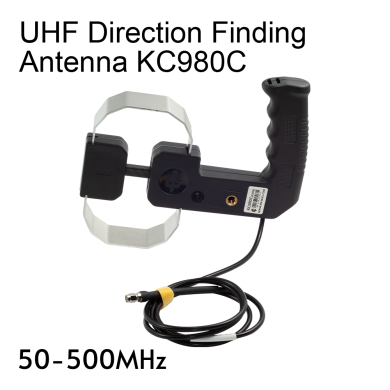
Call 0345 2300 599KC980X represents a series of directional antennas featuring a consistent handle design. They are primarily used as accessories for spectrum analyzers and reconnaissance receivers, supporting applications such as transmitter detection, radio direction finding, near-field electromagnetic interference (EMI) troubleshooting, and, for certain models, field strength measurement. This series is characterized by a wide frequency range, moderate size, ease of portability, and robust construction, making it well suited for handheld use in both indoor and outdoor environments.
As of now, the KC980X series includes the following models:
| Model | Type | Frequency Range |
| KC980A | Shielded Loop | 9kHz~100MHz |
| KC980R | Shielded Loop | 20kHz~400MHz |
| KC980B | Hybrid Loop | 20~200MHz |
| KC980S | Hybrid Loop | 30~350MHz |
| KC980C | Hybrid Loop | 50~500MHz |
| KC980D | Log-Periodic | 350MHz~9GHz |
KC980B, KC980C, and KC980S
All are hybrid-field antennas. A loop with a circumference much smaller than the wavelength is typically a magnetic field antenna and should exhibit a figure-eight radiation pattern. However, if the loop is cut at the midpoint and a resistor is connected in series at the break, the dipoles formed on either side of the break respond to the electric field. Therefore, the response at the feed point is a combination of electric and magnetic field responses. Because these two responses have different phases, with an appropriately chosen resistor, the combined radiation pattern within the nominal frequency range changes from a figure-eight to a cardioid shape. This allows the antenna to be used for direction finding using the major lobe (strong signal peak) method, and at frequencies where nulls occur, the minor lobe (weak signal peak) method can also be applied. This type of antenna was invented around 1972 and is essentially the same as the historical shortwave direction-finding antenna composed of a loop antenna combined with a whip (rod) antenna.
The circumferences of the KC980B, KC980C, and KC980S differ. The B model has the longest circumference, suitable for lower frequencies, exhibiting good directionality from 20 to 200 MHz. Above 250 MHz, the main lobe splits and gradually transitions to the radiation pattern of a dipole antenna. The C model has the shortest circumference, with acceptable directionality from 50 to 500 MHz; its main lobe splits at around 550 MHz, making it suitable for higher frequencies. The S model falls between B and C in circumference, and its gain is also intermediate. Below the lower frequency limit, the antenna behaves like a single-turn inductive coil, with the main lobe splitting and eventually forming a figure-eight pattern perpendicular to the antenna plane.
Gain
The antenna’s main lobe gain increases as frequency rises. The relative variation with frequency is illustrated in the figure below:
![]()
The main lobes of the KC980B, KC980C, and KC980S antennas are relatively broad, so signal level readings should be observed carefully during direction finding. Occasionally, by swinging the antenna and identifying positions on either side where the signal level drops significantly, the location of the major lobe can be estimated.
The theoretical directionality of KC980C is shown below.
![]()
![]()
![]()
![]()
VSWR
Typical VSWR values are as follows:
![]()
Mechanical Parameters
| Name | KC980B | KC980C | KC980S | Remarks |
| Dimensions/mm | 430×295×90 | 220×210×40 | 305×210×40 | Excludes cable |
| Cable Length/m | 1.35 | 1.35 | 1.35 | Measured from handle |
| Net Weight/g | 800 | 350 | 405 | Includes cable |
| Packaging Size/mm | 520×360×130 | 365×265×85 | 365×265×85 | One piece per carton |
| Total Packaging Weight/kg | 1.5 | 0.8 | 0.9 |
Note: Parameters have some random fluctuations and are for reference only.
Shipping:
We have several shipping options for our products, including next-day and Saturday/Sunday delivery for certain items. Please see these options at checkout.
Returns:
If you have any equipment that needs to be returned to Martin Lynch & Sons, please fill out the form below:
Upon receipt of goods you have 14 days to return goods however the goods must be returned in original packaging and care must have been taken with the goods you wish to return. Under distance selling regulations you are not entitled to any refund on carriage charges or modification charges made at your request. Large items cannot be returned if they have been assembled, unless faulty.
Warranty Terms and Conditions
Outside of the 14 faulty return period, returned items cannot be accepted, unless covered by manufacturer's warranty. We will repair as much as possible on site however in exceptional circumstances products may have to be returned to the manufacturer of distributor.
For repairs/replacements under manufacturer’s warranty for any item please download a ML&S return form from the link above and return to ML&S with the faulty product.
International Warranty information
Warranty service for items we sell is available in the U.K. only, unless otherwise noted. It is your responsibility to pay freight for returned items to the U.K. and back to you for desired warranty coverage. All of our NEW products come with a minimum 12 month warranty, (Yaesu & Icom 24 months), with up to 90 days on second-hand equipment. Items returned for service must state "returned goods for repair" on the return air waybill or U.K. import customs duties apply and will be added to your invoice. For more info about returning items please contact our customer help desk, [email protected]