We use
cookies and similar technologies
to help give you the best experience on our site and to show you relevant advertising. If you continue to use this site, we’ll assume that you’re happy to receive all cookies


SIXPAK WITH CONTROLLER, SO-239 CONNECTORS Array Solutions
SKU Part Number:
AS-SIXPAK-WITH-CTRL
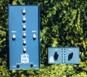
The SixPak has two components: a relay matrix and a control box. The relay matrix allows the selection of any 6 antennas by 2 radios or feedlines....
Read More
Read More
£569.95
£474.96
Pre Order

Seen this product cheaper elsewhere?
Call 0345 2300 599The SixPak has two components: a relay matrix and a control box. The relay matrix allows the selection of any 6 antennas by 2 radios or feedlines. It's lockout circuitry prevents both radios from selecting the same antenna. (The 6X1 type of SixPak is really now replaced by our RATPak remote 6 way antenna switch.) The usual set-up has one SixPak control box, which is manually operated from the radio position. The control box for the 6X2 contains two rotary switches and 12 LEDs, so the operator can see which antennas are selected.
SET UP
6X2 the SixPak can be set up inside or outside the shack. Inside setup of the 6X2 SixPak
is accomplished by wiring two 6-wire cables (rotor cable will work) or just use two
cables with a total of 13 conductors inside from the terminal strips of the SixPak to the
terminal strips in the control box. Wire the control box before you assemble the circuit
board to the box. It will be much easier this way. Radio A is the terminal strip on the left
of the box, and radio B is the terminal strip on the right of the box. The terminal strips are
silk-screen labeled for the 10 to 160 meter bands.
The other end of the cable should be connected to the terminal strip on the SixPak relay
matrix circuit board. It's terminal strips are labeled A10 through A160 and B10 through
B160. Other bands can be substituted. TIP - put a plug like a Cinch™ Jones Plug on
your cables so you can disconnect them during thunder storms.
The SixPak and the control switch box have six #6 hardware fasteners to fasten the
covers to the circuit board tray. Just remove the screws to access the insides of the boxes.
Also take a look at the corners of the SixPak cover if you plan on installing it outside to
verify the paint has sealed the corners of the cover. If not a dab of RTV, or silicon sealant
on the inside should seal it. Leave the bottom open so the box can allow evaporation of
any condensed moisture.
We have had questions as to why I don't ship the switch box assembled. Basically we
used to but we had several switches damaged in shipping, and it’s easier to use the
terminal strips if you don't mount the PCB to the chassis first. It only takes a minuet to
assemble the PCB to the box. It is a fully assembled an soldered circuit card.
Important, Remove Armature keepers – you will see that under the springs of each
relay a small Z bent metal piece. This is an “armature keeper” it prevents the hinging part
of the relay from flying off the hinges during shipping. We have noticed that these pieces
will sometimes prevent the relays from closing properly. Please remove them by taking
the spring off with a small needle nose pliers, slip off the keeper, then put the spring back
on.
Tri-band beams or a multi-band antenna on a single feedline: Connect the wires of the
bands to the SAME terminal of the SixPak relay matrix corresponding to the connector to
which that antenna is attached. The LED will light showing the band being used at the
moment; but the second radio will not be able to use the multi-band antenna because the
lockout will be in effect.
Route all wires through the rubber grommets and holes in the boxes.
The control box has two other terminals: power (marked +12) and ground (GND). Use a
two-wire power cable from a very reliable 12-13.8 VDC power source available in most
amateur radio stations. Current requirements are small 500ma is more than enough.
Please don't use a wall plug mounted 12V supply, because a failure or an accidental
unplugging would open the antenna relay being used and possibly damage an
amplifier.
Connect a wire or a shield of your 6 wire cable to the GND terminal in the control box
and also to the GND terminal in the relay matrix. If mounted outside on your tower use
one or both of the shields in the cable for this purpose. Shielded wire is not necessary and
you may use any good quality cable.
Place the SixPak tray inside the cover and use the #6 hardware supplied to attach the tray
inside the cover. The lower lip of the cover will help protect the connectors from the
elements if mounted outside on the tower. It is to be mounted with the connectors facing
down.
Place the control box circuit board into the rotary switch holes and secure with the
washers and nuts provided for the rotary switches. The 12 LEDs should line up with the
LED holes. Secure the cover of the box with the #6 hardware included.
This completes set-up for the 6X2 configuration.
For Multi-Single or Multi-two contesting stations where the radios are physically
separated it is possible to connect two control boxes in parallel. The LEDs would indicate
to the two operators which bands were being used by the other operator. To use in this
manner the unused A or B rotary switch would be switched to one of the unused
positions. You may want to tape the unused switches to prevent a mistake during the
contest.
ANTENNA and FEEDLINE SET UP
Attach the feedlines from the antennas for the 10m to 160m bands to the corresponding
RF connectors, on the SixPak's tray. Also attach the single or dual radio feedlines to the
RADIO A and RADIO B ports of the SixPak. In the 6X1 configuration the feedline goes
to the Radio A port. If the SixPak is mounted outside on the tower, seal the connection
with your favorite method of sealing RF connectors. The SixPak cover has slots in its
lower lip to accept the galvanized U-bolt supplied for mounting to a tower leg. Mount it
with the RF connectors facing down. Even though its very rugged don't use your SixPak
as a foot step on the tower. Also tape the coax cables to a tower rung or leg to strain
relief them.
USE of AUTOMATIC BAND DECODERS
Alpha Power™ DAS units will supply 12V DC relay voltages to the SixPak directly. Just
wire these outputs in parallel with the corresponding terminals in the switch box. The
rotary switch can be switched out of line by turning the knob to one of the unused 6
positions of the control box. If you have a failure in your decoder you can always go back
to manual control with the rotary switch.
Array Solutions band decoders, Micro-ham decoders, W9XT, and Top Ten Devices and
other band decoders can be used to easily drive the SixPak. We even have a special level
converter board with isolated relays that can be used to drive a SixPak outside remotely
located on a tower.
Key Benefits
Six antennas to two radios, or six antennas to one radio.
Safety interlocked to protect your radios
Saves on hard-line if used on the tower
www.arraysolutions.com - 4 -
High isolation between radios to avoid interference
Amphenol™ Teflon SO-239, or N connectors for reliability
Extremely low insertion loss
Will work to 6 Meters
Can be controlled from Automatic band decoders with 12V outputs
SixPak Specifications
Measurement 14Mhz 30Mhz 50Mhz Comment
Radio to Radio Isolation -82 dB -80 dB -77 dB
signal inserted in one port to
antenna buss, second radio port
measured
Radio to Antenna
Isolation -60 dB -55 dB -50 dB signal connected to antenna on one
side, then opened for measurement
Insertion Loss Radio to
any Antenna port .05 dB .05 dB .2 dB signal inserted into antenna port and
measured at radio port
SWR Radio to any
Antenna port 1:1 1:1 1.15:1
Power Rating all modes
CW, SSB, RTTY 5 KW 5 KW 3 KW This measurement is calculated not
made
Dimensions Relay Box 11.5 X 6 X 3.5 inches 6.5 lbs
Dimensions Control Box 3 X 6 X 3 inches 1 lb
Measurements made with calibrated HP power source, HP power meter, HP spectrum analyzer. These are
typical numbers measured with a production unit.
Shipping:
We have several shipping options for our products, including next-day and Saturday/Sunday delivery for certain items. Please see these options at checkout.
Returns:
If you have any equipment that needs to be returned to Martin Lynch & Sons, please fill out the form below:
Upon receipt of goods you have 14 days to return goods however the goods must be returned in original packaging and care must have been taken with the goods you wish to return. Under distance selling regulations you are not entitled to any refund on carriage charges or modification charges made at your request.
Warranty Terms and Conditions
Outside of the 14 faulty return period, returned items cannot be accepted, unless covered by manufacturer's warranty. We will repair as much as possible on site however in exceptional circumstances products may have to be returned to the manufacturer of distributor.
For repairs/replacements under manufacturer’s warranty for any item please download a ML&S return form from the link above and return to ML&S with the faulty product.
International Warranty information
Warranty service for items we sell is available in the U.K. only, unless otherwise noted. It is your responsibility to pay freight for returned items to the U.K. and back to you for desired warranty coverage. All of our NEW products come with a minimum 12 month warranty, (Yaesu & Icom 24 months), with up to 90 days on second-hand equipment. Items returned for service must state "returned goods for repair" on the return air waybill or U.K. import customs duties apply and will be added to your invoice. For more info about returning items please contact our customer help desk, [email protected]