






RigExpert Stick XPro
Users Manual
“Every job needs the right tool”
Stick XPro is an antenna and cable vector analyzer. The analyzer allows you to measure various parameters of antennas, cables, lines, filters and many others in the frequency range from 100 kHz to 1000 MHz.
The Stick Pro analyzer has a compact size and lightweight, which is great for using the analyzer both in the home and in the field.
The main parameters of the Stick XPro analyzer:
-
- Operating frequency: 100 kHz – 1000 MHz
- Size: 185 * 40 * 33 mm (7,3 in x 1,6 in x 1,3 in)
- Weight: 185 grams (6.5 Oz) (unpacked, with battery installed)
- Type of antenna connector: N-type
- Number of Enter Keys: 6
- Display: color TFT, 220 * 220 pixels.
- Type of battery used: Li-ion 18650 (included)
- PC Connector Type: USB 2.0 Type-C
- Charging Port Type: USB Type-C
- Bluetooth Availability: Yes, Bluetooth ver. 4.2 BLE Single-mode, Class B
- Battery Charge Time: 3 hours.
- RF Power: -10 dBm (at 50 Ohm load)
- Minimum frequency step: 1 kHz
- Operating temperature: 0…40 °C (32…104 °F)
Turning on the analyzer.
The Stick XPro analyzer can be turned on in several ways: – by pressing the  key. – when connecting the analyzer to a PC via a USB cable (the analyzer will turn on automatically). – by long-pressing one of the keys :


 Important! At the same time, the analyzer will turn on and activate the measurement mode to which the pressed key corresponds.
You can turn off the analyzer from any mode by long pressing the key.
Main menu.
After turning on the analyzer, using the key a screen with the main menu of the analyzer is available for the user.
Important! Unlike the Stick 230 analyzer, the Stick XPro analyzer has three main screens with menus.
Screen switching is carried out by short pressing of key.
In addition to service information, at the top of the screen (battery charge, the indication of connection to a PC, charger, Bluetooth connection), the screen displays 4 main measuring functions of the analyzer:
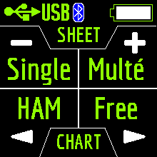
Singe Multé
HAM Free
The Singe and Multé modes display the measurement result as numbers, while the HAM and Free modes display the measurement results as numbers and charts.
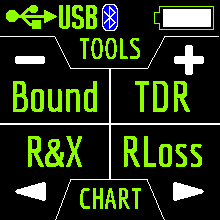
Bound TDR
R&X RLoss
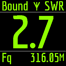
The TDR, R&X and RLoss modes display the result in the form of charts and numbers, and the Bound mode in the form of numbers and color indication.
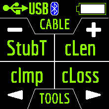
StubT cLen
cImp cLoss
The cImp and cLoss modes display the result in the form of charts and numbers, and StubT and cLen mode in the form of numbers and color indication.
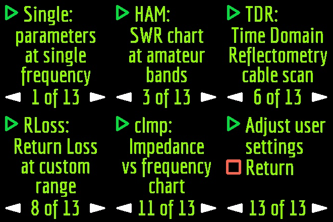
When you press  in the Main Menu, 13 information screens will be available.
The first 12 screens will briefly talk about the main measuring functions of the analyzer (Single, Multé, HAM, Free and others). By pressing the key, you can switch to the corresponding measurement mode.
On the thirteenth screen when you press the key, you will enter the Settings menu.
Single mode.
key.After pressing the key, the measurement will start automatically. This is indicated by a flashing antenna icon located at the top of the screen. You can stop the measurement by pressing
once. You can resume the measurement by pressing once.In Single mode, the analyzer has 5 screens with information.The first screen displays:
- working frequency
- SWR value
- return loss value
The second screen displays:
- working frequency
- |Z| value
- value of active (R) and reactive (X) resistance (taking into account the sign) for the series mode
The third screen displays:
- working frequency
- |Z| value
- inductance (L) and capacitance (C) value for series mode
Important! Sometimes inductance or capacitance values are displayed with a minus sign. It would seem to be contrary to the laws of physics. But no, in RigExpert analyzers, the minus sign next to the value indicates how much inductance or capacitance you need to add to the circuit in order to compensate for the reactive component of the impedance.
On the fourth screen are displayed:
- working frequency
- magnitude
- value of active (R) and reactive (X) resistance (taking into account the sign) for parallel mode
The fifth screen displays:
- working frequency
- phase value
- inductance (L) and capacitance (C) value for parallel mode
Screens switch among themselves by pressing keys.
There are two ways to change the value of the operating frequency:
- keystrokes
 and A single press changes the frequency value minimally. If you press and hold the keys, the frequency will change continuously with an accelerated step.
- pressing and holding the key for 2 seconds. After that, an information window will appear on the analyzer screen. Press key again. A window will appear on the analyzer screen with the setting of the operating frequency. The keys select the cursor position to change units, tens, hundreds, thousands of kHz, and the keys change the value.
A single press of the key saves the change and returns to Single mode.
A single press of the key returns to Single mode without saving changes.
The help menu is accessible by pressing and holding the key and then selecting the Help mode with the keys.
Multé mode.
Table of the dependence of the number of stars on the SWR:5
 – SWR from 1.0 to 1.14 – SWR from 1.1 to 1.153 – SWR from 1.15 to 1.32 – SWR from 1.3 to 1.71 – SWR from 1.7 to 3.0The SWR over 3 analyzer in Multé mode ignores.If, after scanning, the analyzer didn’t find a single resonance, then this means that either your antenna has a minimum SWR of more than 3, or the antenna or coaxial cable is damaged.
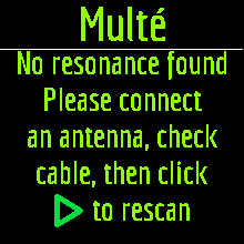
Restarting this mode is possible by pressing any key except key.
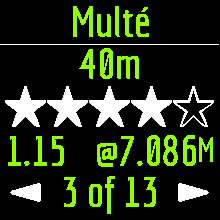
After successful measurement in Multé mode, the following information will be displayed on the analyzer screen:
- band
- number of stars (out of 5)
- a minimum value of SWR and the frequency at which this value was found
If there are more than one results detected by the analyzer, then the screens are switched using the keys.
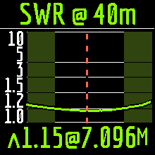
When you press the keys on one of the results screens, the analyzer switches to HAM mode on the same band.
A long press of the key will bring up the Help menu.
HAM mode.
This mode allows you to measure and display the SWR antenna chart on the analyzer screen on one of the fixed HAM radio bands such as:
2.2 km, 630 m, 160 m, 80 m, 60 m, 40 m, 30 m, 20 m, 17 m, 15 m, 12 m, 11 m, 10 m, 6 m, 2 m, 70 cm.
Enabling this mode is possible either from the main menu by pressing the key or when the analyzer is off by a long press of the same key. The measurement will be performed automatically in the range that was used in the previous measurement.
To repeat the measurement, press once. To measure in a cycle, press the key two times at short intervals. A long press of the key will bring up the Help window.
You can change the measuring range using the keys.
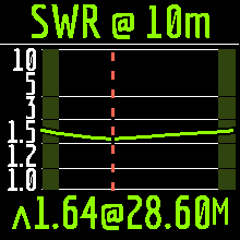
In HAM mode, the SWR icon and the range over which the measurement is carried out are displayed at the top of the screen.
In the center of the screen, a chart of the SWR values for the range is displayed.
The value of the minimum SWR found and the frequency at which this value was found are displayed at the bottom of the screen.
Important! To the left and right of the graph are two vertical stripes. They indicate going out of range. Sometimes the resonance of the antenna may be out of range, but very close to the beginning or end. In such cases, the analyzer will determine the resonance beyond the limits of the ranges.
When you press the or keys the analyzer switches to Free mode with the center frequency of measurement corresponding to the center frequency of the selected range:
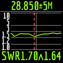
You can exit the mode in the main menu by briefly pressing the key.
Free mode.
This is a classic SWR measurement mode with plotting in a user-defined frequency band.
This mode is useful for survey measurement of the antenna in a wide frequency range or for measuring the SWR in a very narrow predetermined area.
In Free mode, the following is displayed on the analyzer screen:
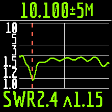
- at the top of the screen: the value of the center frequency of the measurement and the width of the measurement band.
- in the middle of the screen: SWR chart
- at the bottom of the screen: the SWR value under the marker (solid vertical line) and the minimum of the SWR found (dashed vertical line).
There are two ways to set the center of the measurement frequency:
- keys. Pressing the key once will change the frequency discretely to a certain value. Pressing and holding the key will cause an accelerated continuous change in frequency.
- long press After press, a window will be available with a choice of setting the center frequency, exit or calling Help. Press briefly and enter the frequency setting menu.
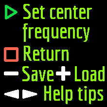
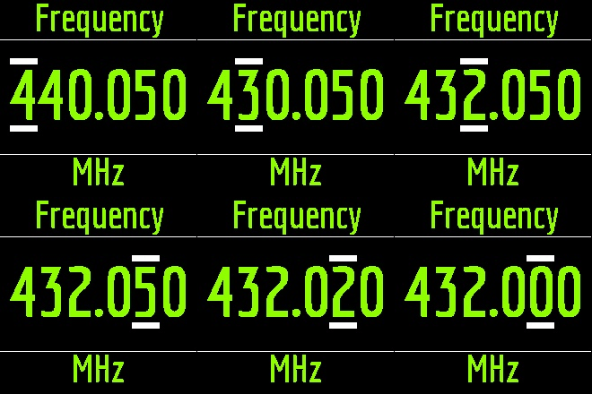
The keys select the cursor position to change units, tens, hundreds, thousands of kHz, and the keys change the value.
Setting the measurement bandwidth by pressing the keys.
The minimum bandwidth is 10 kHz.
A quick double press of the key will cause a measurement in a loop. To stop click key.
To exit the mode, briefly press key.
Analyzer memory usage.
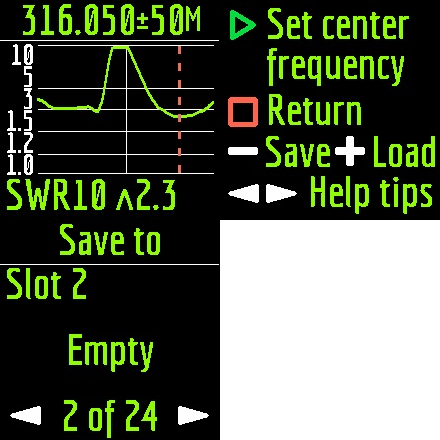
The Stick Pro analyzer has 24 memory cells for storing measurement results from any graphic modes, such as HAM, Free, R&X, Return Loss.
To save the measurement results into memory after plotting the graph, press and hold the key. Then press the key (Save).
Use the keys to select an empty memory slot and press the key.
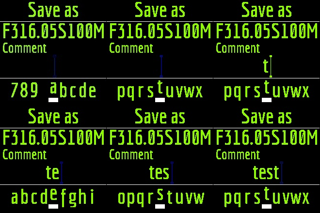
You can name the cell (maximum 13 characters). Use the keys to select a character, the key to adding a character, and the key to delete a character.
Loading results from memory is similar, instead of the key, use the key.
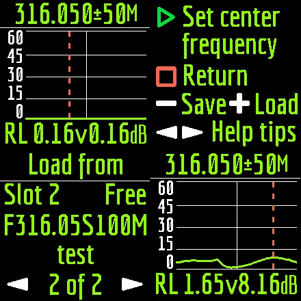
Important! In HAM mode, you can only load measurements that have been taken and saved in this mode.
Bound mode.
The measurement is performed at one frequency.
Set in the settings (long press of the
key) the value of the operating frequency.You can select the measured parameter (SWR or RL) by simultaneously pressing the arrow keys.
Here, set the value below which the measurement will be considered “good”.
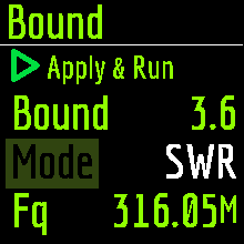 This mode is convenient when you tune the antenna and at the same time visually follow the readings on the analyzer screen. Large print and color alarms will not let you miss out on the best results.

TDR mode.
A short electrical pulse is sent over the line, and then a reflected pulse is observed. By knowing the delay between two pulses, the speed of light, and the cable velocity factor, the DTF (distance to fault) is calculated. The amplitude and the shape of the reflected pulse give the operator idea about the nature of the fault. Time Domain Reflectometers (TDR) are electronic instruments used for locating faults in transmission lines.
A short electrical pulse is sent over the line, and then a reflected pulse is observed. By knowing the delay between two pulses, the speed of light, and the cable velocity factor, the DTF (distance to fault) is calculated. The amplitude and the shape of the reflected pulse give the operator idea about the nature of the fault.Instead of a short pulse, a “step” function may be sent over the cable.
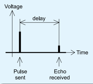
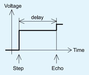 Unlike many other commercially-available reflectometers, Stick Pro does not send pulses into the cable. Instead, another technique is used. First, R and X (the real and the imaginary part of the impedance) are measured over the whole frequency range (up to 600 MHz). Then, the IFFT (Inverse Fast Fourier Transform) is applied to the data. As a result, impulse response and step response are calculated.
This method is often called a “Frequency Domain Reflectometry”, but the “TDR” term is used in this document since all calculations are made internally and the user can only see the final result.The vertical axis of the resulting chart displays the reflection coefficient: Γ= -1 for short load, 0 for matched impedance load (ZLoad=Z0), or +1 for open load. By knowing the cable velocity factor, the horizontal axis is shown in the units of length. Single or multiple discontinuities can be displayed on these charts. While the Impulse Response chart is suitable for measuring distance, the Step Response chart helps in finding the cause of a fault.
Shipping And Returns
Shipping & Delivery
We offer UK and international delivery services, including next working day and selected weekend options for eligible orders. Available services, prices and estimated delivery times are displayed at checkout.
Delivery Information
Delivery options depend on the parcel's size, weight, contents and destination. Express and weekend services are subject to availability and cut-off times. Oversized or exceptionally heavy items may require a specialist delivery quotation.
Returns & Cancellations
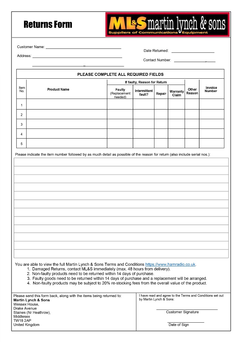
To arrange a return, please contact ML&S or complete our returns form. You may also exercise your statutory right to cancel by email or another clear statement, without completing the form.
Changed Your Mind?
Under the Consumer Contracts Regulations 2013, most purchases made online or by telephone can be cancelled within 14 days of receipt.
You must notify us of your cancellation within this period and return the goods within a further 14 days.
Please handle all goods with care. Returned items must be in a resaleable condition, complete with their original packaging, and all supplied accessories.
You may inspect goods as you would in a shop. Handling beyond what is necessary to inspect them may result in a lawful deduction for diminished value.
Exceptions
Modified Equipment & Reversal Charges
Additional return conditions may apply to equipment modified at the customer's request, including wideband transmit or receive modifications.
ML&S may charge a reasonable fee to reverse physical modifications and restore the equipment to its original factory specification. Any such charge will be agreed in advance and deducted from your refund.
Custom-Made Cable Assemblies
Coaxial cable assemblies manufactured to a customer's specifications are excluded from the 14-day return policy and are non-refundable unless faulty.
Software & Labour Charges
Labour and modification charges requested by the customer are non-refundable once the work has been completed.
Computer software may only be returned under the 14-day return policy if it remains sealed and unopened.
Return Postage Charges
Customers are responsible for the direct cost of returning unwanted or incorrectly ordered goods, where permitted by law. You may arrange your own suitable return postage or use one of our optional prepaid services.
Standard Parcels
Royal Mail Return Label
£5.95
Per parcel
For eligible standard-sized parcels, subject to Royal Mail restrictions. Free collection included.
Larger Parcels
DPD Return Label
£7.95
Per parcel
For larger or heavier parcels and any shipments with batteries.
Collection Service
DPD Collection
£25.00
Per parcel
Available upon request for eligible addresses, subject to availability.
Prepaid return charges will be confirmed before booking and deducted from your refund.
These prices apply to eligible UK mainland returns. Oversized items, specialist products and returns from other destinations may require a separate quotation. Estimated return costs will be disclosed before purchase.
Faulty or Incorrectly Supplied Goods
Return postage charges do not apply to faulty, damaged or incorrectly supplied goods returned under statutory rights. ML&S will arrange a free return in these circumstances.
Refunds
Refunds are processed without undue delay following receipt and inspection of returned goods, and no later than 14 days after we receive goods returned under statutory cancellation rights.
Refunds will be issued to the original payment method. Any prepaid return postage charges or lawful deductions for diminished value will be itemised.
Warranty Terms & Conditions
New Equipment Warranty
Minimum 2-Year Warranty
All new products supplied by ML&S carry a minimum two-year warranty against manufacturing defects, excluding batteries, which are covered by separate warranty terms.
Some manufacturers provide extended warranties, such as the three-year warranty available on eligible Yaesu equipment. Any additional coverage is subject to the manufacturer's terms and conditions.
Our workshop may assess and repair faulty equipment on site or refer it to the manufacturer or an authorised service centre where necessary.
Warranty exclusions may include batteries, normal wear and tear, accidental damage, misuse and unauthorised modifications, as specified in the applicable warranty terms.
All warranties are provided in addition to your statutory consumer rights against ML&S, which are not limited by the warranty period.
International Returns & Warranty
Unless otherwise stated, ML&S warranty servicing is carried out in the UK. International customers must contact us before returning goods to confirm shipping and customs requirements.
International customers are responsible for return postage unless the goods are faulty and ML&S has been notified within a reasonable time.
ML&S accepts no responsibility for additional charges resulting from incorrectly completed customs documentation. Any additional duties charged to ML&S as a result will be billed to the customer before return of the goods.
Need Help With a Return?
Our team can assist with returns, postage arrangements, modifications and warranty claims.
Nothing in these terms excludes or limits your statutory consumer rights.