



Build a Complete QO-100 Ground Station
A practical full-duplex narrowband satellite station built around the Icom IC-9700, DX Patrol Ground Station 2.0 and an 80cm dish.
View Complete Shopping List Shop Satellite EquipmentOperating through an amateur radio satellite might sound like something that requires a garden full of tracking antennas, rotators and specialist microwave equipment. QO-100 is rather different.
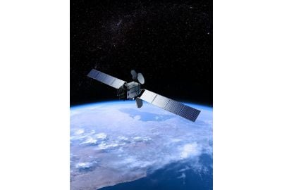
QO-100, also known as Es'hail-2, carries a geostationary amateur radio transponder. Because the satellite appears in a fixed position in the sky, once your dish has been correctly aligned there is no need for an antenna tracking system. This makes it possible to build a permanent satellite station that operates much more like a conventional fixed station.
In this guide we are putting together a complete narrowband QO-100 station around the Icom IC-9700 and DX Patrol Full Duplex QO-100 Ground Station 2.0, together with the dish, feed, coaxial cable, connectors and power supply needed to complete the installation.
The result is a full-duplex station, allowing you to hear your own signal through the satellite while transmitting. This is particularly useful on QO-100 as it allows you to monitor your transmitted signal level, audio quality and frequency position directly from the satellite downlink.
What Do You Need for a Complete QO-100 Station?
For the station described in this guide you will need:
- Icom IC-9700 transceiver
- DX Patrol Full Duplex QO-100 Ground Station 2.0
- DX Patrol High Performance QO-100 Helix
- TRIAX TDS Pro 80A 80cm satellite dish
- Two CT100 75 ohm F Male to F Male cables
- Messi & Paoloni Airborne 10 low-loss 50 ohm transmit coax
- Two N-type Male connectors for the Airborne 10
- Two short Messi & Paoloni Ultraflex 7 IF leads
- One Ultraflex 7 PL-259 connector
- Two Ultraflex 7 SMA Male connectors
- One Ultraflex 7 N-type Male connector
- A suitable 13.8V DC power supply
The modified QO-100 LNB, GPS antenna and Ground Station DC cable are supplied with the DX Patrol Ground Station 2.0, so these do not need to be purchased separately.
1. The Radio, Icom IC-9700
At the heart of the station is the Icom IC-9700. It is particularly well suited to this type of installation because it provides all-mode operation on 2m, 70cm and 23cm together with proper full-duplex operation.
The IC-9700 does not transmit directly on the QO-100 2.4GHz uplink or receive the approximately 10GHz satellite downlink. Instead, the radio operates at an intermediate frequency, normally shortened to IF, while the DX Patrol Ground Station performs the microwave frequency conversion.
For the full-duplex arrangement in this guide we use:
- 2m for transmit IF, within the Ground Station's 144.500 to 145.000MHz IF range
- 70cm for receive IF, within the Ground Station's 432.500 to 433.000MHz IF range
Using separate bands allows the IC-9700 to transmit and receive simultaneously. The 144MHz antenna socket uses a PL-259 connection and the 430MHz antenna socket uses an N-type connection, which determines the connectors required for our two short IF leads.
2. DX Patrol Full Duplex QO-100 Ground Station 2.0
The DX Patrol Full Duplex QO-100 Ground Station 2.0 is the part that makes the station comparatively straightforward to assemble.
It takes the lower-frequency IF signal from the IC-9700 and converts it to the QO-100 uplink between 2400.000 and 2400.500MHz. On receive it converts the satellite downlink between 10489.500 and 10490.000MHz back down to a frequency that the IC-9700 can receive.
The Ground Station 2.0 includes:
- Full-duplex transmit and receive operation
- Up to 10W RF output at 2.4GHz
- Internal GPS-locked frequency reference
- Modified QO-100 LNB
- GPS antenna
- DC power cable
- Selectable IF bands from 10m through to 23cm
- SWR, voltage, temperature and current protection
The supplied modified LNB is important. You do not need to purchase another DX Patrol QO-100 LNB when using this Ground Station package.
3. TRIAX TDS Pro 80A 80cm Satellite Dish
At the antenna end of the station we are using the TRIAX TDS Pro 80A, an 80cm offset satellite dish designed for Ku-band reception.
Its 80cm reflector provides a useful amount of aperture for a permanent QO-100 installation without requiring an excessively large dish. It also has a standard 40mm LNB mounting arrangement and an aluminium feed arm, making it a practical platform for the DX Patrol Helix and modified LNB.
Unlike low Earth orbit amateur satellites, QO-100 does not travel across the sky from the operator's point of view. Once the TRIAX dish has been correctly aligned and tightened in position, no rotator or automatic satellite tracking system is required during normal use.
The dish includes its mounting bracket and mast clamps, although the exact pole, wall bracket or other supporting structure required will depend on the installation.
4. DX Patrol High Performance QO-100 Helix
A conventional satellite television LNB deals with the receive side of the system, but transmitting to QO-100 requires a suitable 2.4GHz feed at the focal point of the dish.
The DX Patrol High Performance QO-100 Helix is a four-turn helical antenna designed specifically for this purpose. It provides the circular polarisation required for the uplink and is designed to work with an LNB fitted through the centre of the assembly.
This allows one dish assembly to handle both sides of the station:
- Transmit: 2.4GHz from the Ground Station through the Helix
- Receive: approximately 10GHz from QO-100 through the modified LNB
The Helix has an N-type RF connection, making it suitable for connection to a proper low-loss 50 ohm coaxial feeder.
Although the Helix itself is normally supplied without an LNB, this is not a problem in this installation because the required modified LNB is already supplied with the DX Patrol Ground Station 2.0.
5. Two CT100 75 Ohm Cables for the LNB
The receive and reference connections between the Ground Station and modified LNB use 75 ohm satellite coax, rather than the 50 ohm coax normally found in an amateur radio station.
For this installation you need two CT100 F Male to F Male cables. In most installations both should be ordered in the same length, long enough to run between the Ground Station in the shack and the LNB on the dish.
The two cables have separate jobs:
- LNB signal cable: carries the received satellite signal from the modified LNB back to the Ground Station SIGNAL IN connection.
- 25MHz reference cable: carries the Ground Station local oscillator reference to the modified LNB.
Our VDC-CT100-FF leads use 75 ohm CT100 coaxial cable with F Male connectors already fitted and are available in a selection of lengths.
6. Low-Loss 2.4GHz Transmit Coax
The coaxial cable between the DX Patrol Ground Station and the Helix is one of the most important parts of the installation.
At 2.4GHz, feeder loss becomes considerably more significant than it is on HF. There is little benefit in producing RF power in the shack if a large proportion of it is then lost as heat in the coax before it reaches the dish.
For this connection we recommend Messi & Paoloni Airborne 10. It is a 10.3mm low-loss 50 ohm coax designed for demanding RF applications and outdoor installation.
The connection is:
DX Patrol Ground Station RF OUT to N Male connector to Airborne 10 to N Male connector to DX Patrol Helix.
You therefore need enough Airborne 10 to reach from the Ground Station to the dish and two suitable N Male connectors.
Keep the 2.4GHz coax run as short as is reasonably practical. The shorter the feeder, the more of the Ground Station's RF output reaches the Helix.
View Messi & Paoloni Airborne 10 View Airborne 10 N-Type Connectors
7. IF Patch Leads Between the IC-9700 and Ground Station
Two short 50 ohm coaxial leads complete the full-duplex connection between the IC-9700 and DX Patrol Ground Station.
These leads are only travelling around the shack rather than all the way to the dish, so approximately one metre per lead is usually sufficient for a neat installation.
Transmit IF Lead
The transmit IF comes from the IC-9700's 144MHz antenna socket and connects to the Ground Station IF-TX/RX input.
The required cable is:
IC-9700 144MHz SO-239 to PL-259 to Ultraflex 7 to SMA Male to DX Patrol Ground Station IF-TX/RX.
Receive IF Lead
The dedicated receive output from the Ground Station connects to the IC-9700's 430MHz antenna input.
The required cable is:
DX Patrol Ground Station RX to SMA Male to Ultraflex 7 to N Male to IC-9700 430MHz antenna socket.
For the pair of leads you will therefore need approximately two metres of Ultraflex 7 in total, two SMA Male connectors, one PL-259 and one N Male connector.
View Messi & Paoloni Ultraflex 7 View Ultraflex 7 PL-259 View Ultraflex 7 SMA Male View Ultraflex 7 N-Type Male
8. Powering the Station
Both the IC-9700 and DX Patrol Ground Station require a suitable 13.8V DC supply.
Because the IC-9700 itself can draw substantial current during transmission and the Ground Station also requires its own DC supply, it is sensible to use a power supply with plenty of headroom if both units are going to share one supply.
For this complete station we recommend the MyDEL MP-50SWIV. Its 50A output capacity provides considerably more headroom than a smaller 20A or 25A supply and allows both the radio and Ground Station to be powered from the same main station supply.
As with any station DC system, use correctly rated cable, suitable fusing and proper connections between the power supply and equipment.
How Everything Connects
Follow each signal path independently when wiring the station. Check the connector types and input/output labels against the equipment documentation.
Once all of the individual components are together, the station becomes much easier to understand if it is broken down into four separate signal paths.
Transmit Path
IC-9700 144MHz output to Ultraflex 7 IF lead to DX Patrol Ground Station to 2.4GHz Airborne 10 feeder to DX Patrol Helix to TRIAX dish to QO-100.
Receive Path
QO-100 to TRIAX dish to modified LNB to CT100 signal cable to DX Patrol Ground Station to Ultraflex 7 receive IF lead to IC-9700 430MHz input.
LNB Reference Path
DX Patrol Ground Station 25MHz reference output to second CT100 cable to modified QO-100 LNB.
GPS Reference
The GPS antenna supplied with the Ground Station connects directly to the Ground Station and should be positioned where it has a suitable view of the sky. The Ground Station uses its GPS-locked internal reference to provide a stable frequency reference for QO-100 operation.
Why Full Duplex Matters
With the transmit and receive IF paths connected separately, the IC-9700 can receive the QO-100 downlink while you are transmitting.
This means you can hear your own signal after it has travelled through the satellite, making it much easier to check your audio, frequency and signal strength rather than relying entirely on another operator for a report.
Complete QO-100 Shopping List
| Product | Quantity | Purpose | Link |
|---|---|---|---|
| Icom IC-9700 | 1 | Full-duplex IF transceiver | View Product |
| DX Patrol Ground Station 2.0 | 1 | QO-100 transmit and receive conversion | View Product |
| DX Patrol QO-100 Helix | 1 | 2.4GHz transmitting dish feed | View Product |
| TRIAX TDS Pro 80A | 1 | 80cm satellite dish | View Product |
| VDC-CT100-FF | 2 | LNB received signal and 25MHz reference | View Product |
| Messi & Paoloni Airborne 10 | As required | Low-loss 2.4GHz transmit feeder | View Product |
| Airborne 10 N Male Connector | 2 | Ground Station to Helix feeder | View Product |
| Messi & Paoloni Ultraflex 7 | Approx. 2m total | Two short 50 ohm IF leads | View Product |
| Ultraflex 7 PL-259 | 1 | IC-9700 144MHz transmit IF connection | View Product |
| Ultraflex 7 SMA Male | 2 | Ground Station IF connections | View Product |
| Ultraflex 7 N-Type Male | 1 | IC-9700 430MHz receive IF connection | View Product |
| MyDEL MP-50SWIV | 1 | 13.8V station power supply | View Product |
Why Cable Choice Matters on QO-100
At HF, a few metres of average coaxial cable might make relatively little practical difference. At 2.4GHz, cable loss becomes a much more important part of the station design.
That is why the transmit side of this installation uses Messi & Paoloni Airborne 10. It keeps losses between the Ground Station and the Helix as low as reasonably possible without moving the entire transmitting system outside next to the dish.
The LNB side is different. It is designed to use 75 ohm satellite coax, which is why the two CT100 F Male to F Male leads are used for the received signal and local oscillator reference.
Use properly fitted connectors, avoid unnecessarily long cable runs and weatherproof any outdoor RF connections. On a microwave installation, seemingly small losses can have a much greater effect than they would on an HF station.
Setting Up the Dish
Once the equipment is connected, the next stage is accurately aligning the TRIAX dish with QO-100.
Take your time with the alignment. Small adjustments to azimuth, elevation and feed position can make a noticeable difference at these frequencies. Peak the received QO-100 beacon before finally tightening the dish and feed assembly.
The feed and LNB position are also important. Once the strongest and most consistent received signal has been found, make sure all fittings are secure and any outdoor coaxial connections are suitably protected from the weather.
Once the dish is correctly aligned, the advantage of QO-100 being geostationary becomes obvious. It remains pointing at the same part of the sky, so the dish can stay fixed in position rather than following a satellite from horizon to horizon.
Before Your First Transmission
Before transmitting, double-check the complete RF path and make sure the IC-9700 output power is set correctly for the Ground Station.
In particular:
- Make sure the Ground Station RF output is connected to the Helix before transmitting.
- Make sure the LNB cables are connected to the correct Ground Station ports.
- Do not make or change LNB coax connections while the Ground Station is powered.
- Set the IC-9700 transmit power to its lowest suitable setting before transmitting into the Ground Station.
- Never exceed the Ground Station's 5W maximum IF input.
- Use full-duplex receive monitoring to check your own QO-100 downlink signal.
The Ground Station is factory configured for around 500mW drive for VOX operation, which makes the low-power end of the IC-9700 particularly useful for this installation.
Operating Through QO-100
The QO-100 narrowband transponder can be used for modes including SSB, CW and suitable narrowband digital modes.
Always follow the current QO-100 band plan and operating guidance. In particular, use only the RF power required to produce a suitable downlink signal and monitor your own transmission using the station's full-duplex capability.
Wide signals should not be transmitted through the narrowband transponder.
A Complete QO-100 Station Without Building Your Own Microwave Hardware
QO-100 is one of the most interesting ways of combining conventional amateur radio operating with microwave and satellite technology.
The combination of an Icom IC-9700, DX Patrol Full Duplex Ground Station 2.0, DX Patrol Helix and TRIAX 80cm dish removes much of the complexity traditionally associated with building a microwave satellite station.
Add the correct 75 ohm LNB cables, a low-loss 2.4GHz feeder, the two short IF leads and a suitably rated power supply and you have the basis of a complete permanent full-duplex QO-100 station.
The important thing is to treat the station as one complete RF system. The radio, transverter, dish, feed, LNB, coaxial cable, connectors and power supply all contribute to how well the finished station performs.
Browse Satellite Equipment at ML&S
Written for the ML&S Blog, Top Tips